��������ģ���·��LM3914��ʾ ���� Ϊ�û��ṩ�ɱ���ԡ�
�����������Ұ뵼�幫˾���ϲ�ƷLM3914��/��״��ʾ������������20�����ˣ����Ա��㷺Ӧ�á�LM3914���Ը�֪ģ���ѹ����ͨ����״ģʽ����10�� LED �е�һ������������ͼģʽ�������LED�ķ�������ʾ��ѹ��С��������и�Ӧ����Ҫ��ʾģ�������ѹ��Ҫ��������Ի�����̶ȸ�ʽ��10�����ϵȼ���LED��ʾ������ LM3914�������ֲᣬ���Խ����3914�������Ӷ����10������LED����ʾ���ο�����1��������ʹ��ô����LM3914Ҳֻ��������ʾ�����ѹ�����༭ע���������Ұ뵼�廹�ṩ LM3915������һ�������3dB�����棬��LM3916������ƵӦ�ã���������λ��ʾ���롣��
������Ӧ�õ�Ҫ��LM3914�ṩ������ԣ�ʹ��һ������Atmel AVRϵ��ATTiny13 ������ ��·�������1kB����洢����һ����ͨ��10λADC���Լ�6��ͨ��I/O �ڡ�������·�̼��Ϳ���ʵ��0~5V�����ѹ��Χ�ڵ����Ի������ת����
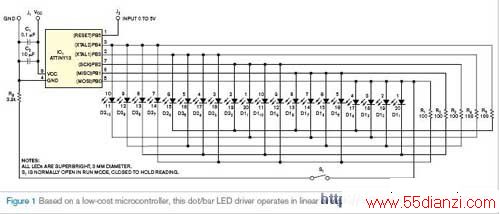
����ͼ1�е�·��20��LED������ʾ�����ѹ��������S1�ر�ʱ������ʾ������������ˮƽ�Ķ����ϡ�������6��I/O���е�5������������20��LED�Ϳ��ء�ʣ�µ�I/O�����ó�ADC����ͨ��������ģ�������ѹ������������ Charlieplexing�ķ���������һ����I/O�����������N��(N-1)��LED�ķ�������ֻ�ã���I/O�ھͿ�������20�� LED���ο�����2 ~ 4����
�����̼���C���Ա�д������AVR-GCC���룬����Windows��Linux�汾��C�ͻ��������������������ʹ�ÿ������� �����ж�����ģʽ��Tiny13���ڲ�10λADC����ģ�������ѹת������������ÿ��ת�����ʱ��ADC ����һ�����ӳ�������жϣ�����жϽ� ADCת��������������һ�����������С�
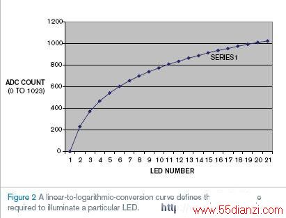
����Ϊ��������˸����ʾ��һ���ڲ���ʱ����9.6MHzϵͳʱ�Ӳ���һ��1875Hz���жϣ��Դ���90Hz������������·LED����ADC����ֵ����һ�������õ������ѹ��������ʾ���ò��ұ�����ADC��������������ʾ��ͼ2��ʾȷ���ò��ұ�ֵ�Ķ���ת�����ߡ��������ԺͶ�����ʾ�� ATTiny13���Ƴ���汾���ɴӱ����ʵ�������ء��ɶ�Դ�������ģ���ֻ��ʾ0V~5V�����ѹ�е�ij�������䡣���磬�����趨1V~3VΪ������ʾ��Χ����2V ~ 3V�����ѹΪ������ʾ��
����Ӣ��ԭ�ģ�
����MICrocontroller drives logarithmic/linear dot/bar 20-LED display
����Do-it-yourself analog-to-LM3914 display driver offers user programmability.
����Dhananjay V Gadre and Anurag Chugh, Netaji Subhas Institute of Technology, New Delhi, India; Edited by Brad Thompson and Fran Granville -- EDN, 1/18/2007
����Available for more than 20 years, National SEMIconductor's venerable LM3914 dot/bar-display driver still enjoys wide popularity among designers. The LM3914 CAN sense an analog voltage level and display it on 10 LEDs by illuminating one of 10 in dot mode or by progressively illuminating LEDs in bar-graph mode. Recently, an application needed an analog-input-voltage display capable of displaying more than 10 levels in linear- and logarithmic-scale formats. According to the LM3914's data sheet, you can cascade multiple 3914s to display more than 10 levels (Reference 1), but, even so, the LM3914 offers only linear displays of its input voltage. (Editor's note: National Semiconductor also offers the LM3915, a logarithmic, 3-dB-per-step version, and the LM3916, which displays its input in volume units, for audio applications.)
www.55dianzi.com
����This applICation required more flexibility than the LM3914 offers, and it uses a circuit based on an Atmel AVR-family ATTiny13 microcontroller, which features 1 kbyte of program memory; a four-channel, 10-bit ADC; and six general-purpose I/O PINs. ALTEring the circuit's firmware allows linear or logarithmic scaling o f the 0 to 5V input-voltage range.
����The circuit in Figure 1 continuously displays the input voltage in 20 levels. When closed, switch S1 freezes the displayed reading at its then-current level. Five of the microcontroller's six I/O pins control all 20 LED s and the switch. Configured as an ADC-input channel, the remaining I/O pin receives the analog-input voltage. The microcontroller uses Charlieplexing, a method of using I/O lines to drive as many as N��(N�C1) LEDs, to drive 20 LEDs with only five I/O pins (references 2 through 4).
����The firmware is written in C and compiled using AVR-GCC, a freeware C compiler and assembler available in Windows and Linux versions. It uses the Tiny13's internal 10-bit ADC operating in free-running, interrupt-driven mode to convert the analog-input voltage into a digital number. Upon completion of each conversion, the ADC generates an interrupt that a subroutine reads; the interrupt stores the ADC's converted output in a shared variable.
����To provide a flicker-free display, an internal timer generates a 1875-Hz interrupt derived from the 9.6-MHz system cLOCk to drive the multiplexed LEDs at a rate exceeding 90 Hz. Dividing the ADC count by a constant yiELDs a linear display of the input voltage. A look-up table scales the ADC count to produce a logarithmic display. Figure 2 shows the logarithmic-conversion curve that defines the look-up table's values. Versions of the ATTiny13's control programs for linear and logarithmic scales are available for downloading from this Design Idea. You CAN modify the source code to display only a particular subrange of the input voltage of 0 to 5V. For example, you can specify a linear-display range spanning 1 to 3V or a logarithmic scale for input voltages of 2 to 3V.
����References
����1.LM3914 data sheet.
����2.Lancaster, Don, "Tech Musings," August 2001.
����3."Charlieplexing: Reduced Pin-Count LED Multiplexing," Maxim Application Note 1880, Feb 10, 2003.
����4.Benabadji, Noureddine, "PIC microprocessor drives 20-LED dot- or bar-graph display," EDN, Sept 1, 2006, pg 71.
����Ӣ��ԭ�ĵ�ַ�� http://www.edn.com/article/CA6406730.html
���Ĺؼ��֣������� DSP/FPGA��������Ƭ��-�����豸 - DSP/FPGA����


