Abstract: This article describes an automated data collection system for analog-to-digital converters (ADCs). It discusses the advantages of automating data collection as well as a detailed deSCRJPTion of the hardware and software. It goes on to explain the operation of the system and give some data examples.
Introduction
In order to characterize data converters more efficiently and with better repeatability, a laboratory test setup can be automated. There are three key advantages:
- Since the software configures the test equipment, the same instrument settings are used each time a part is characterized.
- When the software captures data, it stores it in a file, automatically eliminating errors due to incorrect data entry. When taking data manually, all of the data must be written by hand and then manually entered into a file or spreadsheet. These steps are tedious and potential sources of error.
- Since the PC is driving the measurement and data collection process, data is gathered much faster than can be accomplished manually. Thousands of data points can be acquired in minutes. Manually it could take several days to gather the same amount of data. Once the data is in the designated file, it can be saved as a text file so that it can easily be evaluated or plotted using software programs such as Gnuplot or Excel.
Since most lab instruments have the general purpose interface bus (GPIB) interface, practically any manual lab measurement can be automated.
Background on GPIB
Originally developed by Hewlett Packard as HP-IB, GPIB is a high-speed communication interface which allows interconnection and control of programmable instruments. A controller card, which often resides in a PC, controls a wide variety of test instruments such as logic analyzers, signal and data generators, digital voltmeters, and power supplies. GPIB was standardized by the IEEE and is now known by the three names GPIB, HP-IB, and IEEE-488 bus. Further information regarding GPIB can be found on the world wide web at http://www.ni.com (National Instruments) or http://www.hit.bme.hu/people/papay/edu/GPIB/tutor.htm.
Advantages Of An Automated Setup
One advantage of using an automated test setup is that it speeds up the task of characterizing parts. Ideally, the software should be written and debugged in advance, so that when parts are available, valuable time is not spent writing and debugging software code. For our test setup, Visual C++ was selected as the programming language.
With a functional automated test setup, some of the more difficult data converter plots such as integral non-linearity ( INL), differential non-linearity (DNL), and fast Fourier transform (FFT) plots can be made available within minutes.
Modular software allows re-use for other programs. With flexible code, the software can be easily modified for other converters with different speeds and resolutions.
Another key advantage of an automated setup is that the design engineer doesn't need to know the equipment and instruments intimately since the software automatically programs all of the instrument settings. Although a fundamental knowledge of the equipment is still essential to insure accurate results. While the tests are running, the engineer often does not have to be physically present. Often, the tasks of supervising tests and obtaining data are delegated to a lab technician, thus freeing up the engineer even more.
Setup Requirements
GPIB Interface Card
The GPIB interface card plugs into one of the PC expansion slots and allows the PC to communicate with any test instrument that has a GPIB Interface. One GPIB cable is necessary for each instrument. The instruments are interconnected using a serial daisy-chain starting from the PC and ending at the last instrument. Each instrument requires a unique GPIB address. The available addresses are 0 through 31. The number of instruments that can be on the GPIB Bus depends on the length of cables and how they are connected. In practical applications up to 10 instruments have been connected at the same time.
Pattern Generator
The pattern generator creates all of the I/O data patterns used to communicate with the device-under-test (DUT). Since, in this example, the ADC has a serial output, the pattern generator is also used to provide the signals that control the timing for the de-serializer board. A de-serializer board allows the logic analyzer memory to be used more efficiently. The serial peripherals interface (SPI) signals (clock, data, and chip-select) are derived from the pattern generator. For the two-wire I²C interface, the clock and data signals are generated. Since the I²C data line is bi-directional, a circuit with open collector buffers is required.
The data patterns are loaded via the GPIB interface. The GPIB interface also controls the setup of the pattern generator.
Logic Analyzer
For an ADC, the logic analyzer is used to capture the conversion data and store it in a file. Setup of the logic analyzer is controlled by the GPIB, but due to speed constraints of the GPIB our data file was transferred to the PC through a local area network (LAN).
Signal or Pulse Generators
Two signal/pulse generators are necessary. One is used to generate the conversion clock (or sample frequency). The other is used to generate the ADC input signal (or test frequency). The signals from both units should be synchronized. This is called coherent testing. Note that the conversion clock generator drives the pattern generator.
Power Supplies
Supply voltages need to provide power to the DUT and the de-serializer board. These supplies can be programmable if desired to further automate the test setup.
DC Power Source
A clean DC power source is needed to provide voltage reference for the ADC or DAC. The Datel Calibrator was used in our setup.
De-Serializer Board
This circuit is used to convert the serial data output of an ADC to a parallel format, so that the data can be captured by the logic analyzer more efficiently. Although the data could be deserialized by the code, the parallel format makes better use of the logic analyzer memory.
Figure 1 illustrates how the instruments are interconnected to the PC and to each other. For parallel interface ADCs, the de-serializer board is not needed.
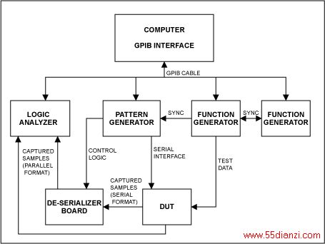
Figure 1. Interconnection of equipment for serial or parallel-output ADC.
Software
The software was developed using Visual C++ and is compatible with Win95/98 or WINOOWs NT. The programs were all written in WINOOWs using the GUI interface, making it user-friendly.
One of the key features of the software is the initialization feature called INIT or SETUP (see Figure 3). When the operator clicks on this feature, it sets up the correct patterns in the pattern generator, and sets up the logic analyzer so that it is ready to capture the data. The operator never has to touch the instruments other than to make sure that they are powered up and connected properly.
The software allows the operator to select the converter sample rate and the resolution of the device. It also allows control of the number of samples taken. While the conversions are occurring, the data is written to a file.
There are two programs used, one for control and data acquisition, and the second for analyzing the data. The control and acquisition program controls the data generator and acquires data from the logic analyzer. The analysis software calculates INL, DNL, and FFTs.
[1] [2] 下一页
本文关键字:数据采集 电工文摘,电工技术 - 电工文摘


