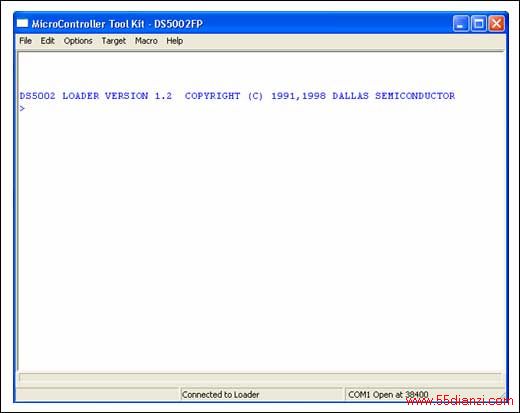
> Loading File ...\DS8007-1.hex
通过显示一连串的圆点表示正在装载。
// file DS8007-2.c//#include <REG5000.H> // special function register declarations// // for the DS5000/5002 #include <string.h>#include "LCD_Funct.h" int tmp = 0; uint8_t LCD_Str[42];void main(void){ // Initialize LCD Module, and display 2-line message. LCD_Init(); strcpy(LCD_Str, "DS8007 Dual"); // Create first line of LCD text tmp = LCD_Curpos(1,5); // POSTTTION cursor line 1 char 5 if (tmp == 0) LCD_WRStr(LCD_Str); // Write string to LCD strcpy(LCD_Str, "Smart Card Interface"); // Create 2nd line of LCD text tmp = LCD_Curpos(2,1); // POSTTTION cursor on line 2, char 1 if (tmp == 0) LCD_WRStr(LCD_Str); // Write string to LCD tmp = LCD_Curpos(1,20); // Return cursor to line 1 char 20 while (1); // Loop here to end program}void LCD_Init(){ LCD_Delay(); // Delay to ensure that LCD power-up is complete LCD_WRCmd(FnctSet); // Write FnctSet instruction LCD_WRCmd(DispCnt); // Write Display Control instruction LCD_WRCmd(DispClear); // Write Display Clear instruction LCD_WRCmd(EntryMode); // Write Entry Mode instruction}// Write a string to the 2 x 20 LCD modulevoid LCD_WRStr(uint8_t LCD_Str[]){ int i = 0; while ((LCD_Str[i] != '\0') && (i < 20)) { LCD_WRChr(LCD_Str[i]) ; // Write first 20 characters i++; } if (LCD_Str[i] != '\0') LCD_WRCmd(Line2Ad); // Set CGRAM address to first char 2nd line while ((LCD_Str[i] != '\0') && (i < 40)) { LCD_WRChr(LCD_Str[i]) ; i++; }}// Write a single character to the 2 x 20 LCD modulevoid LCD_WRChr(uint8_t LCD_Chr){ LCD_Busy(); // Wait until the LCD is not busy LCD_RS = 1; // Set RS high for character write LCD_Dat = LCD_Chr; // Output character LCD_EN = 1; // Set enable high LCD_EN = 0; // Clear enable LCD_RS = 0; LCD_Dat = 0xFF; // Re-establish Port Pins as inputs}// Write a command to the 2 x 20 LCD modulevoid LCD_WRCmd(uint8_t LCD_Cmd){ LCD_EN = 0; // Make sure that the LCD enable is low LCD_RS = 0; // Set LCD register select and R/W lines LCD_RW = 0; LCD_Busy(); // Make sure that the display is not busy LCD_Dat = LCD_Cmd; // Output instruction LCD_EN = 1; // Set enable high LCD_EN = 0; // Clear enable LCD_Dat = 0xFF; // Re-establish Port Pins as inputs}// Set the cursor POSTTTION to a specific LOCAIIONint LCD_Curpos(uint8_t VPos, uint8_t HPos){ int rtn; uint8_t Addr, Cmd; // Check input range 1..2 line, 1..20 characters per line if (((VPos == 0) || (VPos > 2)) || ((HPos == 0) || (HPos > 20))) rtn = -1; else { if(VPos == 2) Addr = (0x40 + (HPos - 1)); else Addr = HPos - 1; rtn = 0; Cmd = Addr | 0x80; LCD_WRCmd(Cmd); } return(rtn); }// Test the LCD Module to see if it is Busy (loop until// not busy) void LCD_Busy(){ uint8_t LCD_Stat = LCD_Dat; // Get byte containing status while (LCD_Stat & 0x80){ // Wait for busy flag to clear LCD_RW = 1; // LCD RW needs to be high LCD_EN = 1; // Strobe enable signal LCD_Stat = LCD_Dat; // Read staus LCD_EN = 0; LCD_RW = 0; }}// Time delay for 2 x 20 LCD module (approximately 50ms)void LCD_Delay(){ uint8_t i, j ; for (i=0;i!=100;i++) { for (j=0;j!=153;j++); }}
本文关键字:评估 电工文摘,电工技术 - 电工文摘
上一篇:DS8007在智能卡交易中的应用


