group hash check, and promiscuous mode), pattern matching, insertion with expansion or replacement for transmit frames, VLAN tag insertion, RMON statistics, local bus master DMA for deSCRJPTor fetching and buffer access, and optional multiplexing with GPIO (MII/RMII/SMII) or DSI/system bus signals lines (MII/RMII).
UART with full-duplex operation up to 6.25 Mbps.
Up to 32 general-purpose input/output (GPIO) ports.
I2C interface that allows booting from EEPROM devices.
Two timer modules, each with sixteen configurable 16-bit timers.
Eight programmable hardware semaphores.
Global interrupt controller (GIC) with interrupt consolidation and routing to INT_OUT, NMI_OUT, and the cores; twenty-four virtual maskable interrupts (8 per core) and three virtual NMI (one per core) that can be generated by a simple write access.
Optional booting external memory, external host, UART, TDM, or I2C.
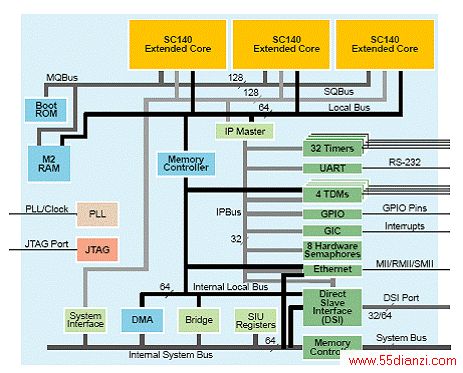
图1.MSC8113方框图图1.MSC8113方框图
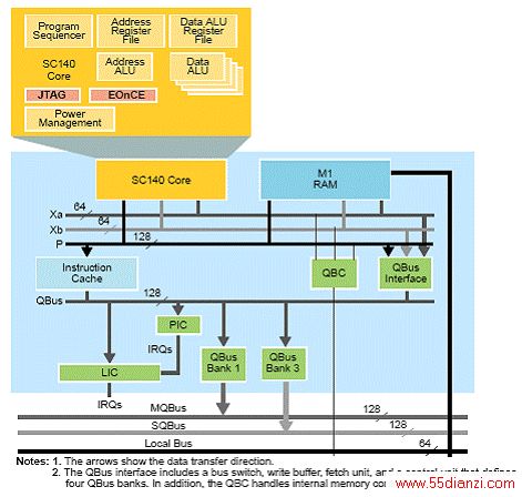
图2.StarCore SC140 DSP 扩展内核方框图
Freescale supplies a complete set of DSP development tools for the MSC8113 device. Our tools are focused on providing easier and more robust ways for designers to develop optimized DSP systems. Whether the application targets IP telephony or media gateways, the development environment gives the designers everything they need to exploit the advanced capabilities of the MSC8113 architecture.
The MSC8113 tool components include the following:
Integrated development environment (IDE). Easy-to-use graphical user interface and project manager for configuring and managing multiple build configurations.
C compiler with in-line assembly. The developer can generate highly optimized DSP code by exploiting the StarCore multiple-ALU architecture, with parallel fetch sets and high code density.
Librarian. The developer can create application-specific DSP libraries for modularity.
Linker. The developer can efficiently produce executables from object code and partition memory according to the application architecture; the linker supports code overlay.
Debugger. Seamlessly integrated real-time, non-intrusive, multi-mode and multi-DSP debugger handles highly optimized DSP algorithms. The developer can choose to debug in source code, assembly code, or mixed mode. Supports RTOS-aware debugger.
Royalty-free RTOS. Included with package.
Software Simulator. Full chip simulation; the developer can design an application and run it on the simulator before running it on the silicon. FCS integrated under IDE, the simulator provides customers with tools to create projects and debug them as they would on silicon.
Profiler. The developer can analyze and identify program design inefficiencies.
Data Visualization. Lets the developer graph variables, registers, regions of memory, and HSST data streams as they change over time. By changing the visualization filter, you can plot this data in a variety of ways; including line charts, logarithmic charts, polar coordinates, and scatter graphs.
High Speed Run Control. PowerTAP high speed host-target interface allows users to program in Flash memory, ROM, and cache.
Host Platform Support. Microsoft WINOOWs and Solaris.
Development Board. The application development system (ADS).
Kit for MSC8113. A complete system for developing and debugging real-time hardware and software. The kit includes the MSC8113 device with a companion memory, JTAG debug interface,Ethernet interface, PCI interface, digital video interfaces and software device drivers.
Example Application: 672 G.711-Channel Media Gateway
The Media Gateway application shown in Figure 1 can process ~512 G.711 channels. The IP interface uses either UTOPIA or 100BaseT connected to the MSC8103 device that is the array aggregator. The MSC8113 performs the translation between the packet world and the PSTN world and the synchronous data is connected to the PSTN world through the TDM interface with a time slot assigner translating to protocols such as H.110 and MVIP. The MSC8103 DMA controller directly accesses the M1 and the M2 memories of the MSC8113 device through its local bus using its UPM. In parallel, it uses its system interface for accessing its SDRAM and flash. In this application 32-bit data DSI is sufficient, so the MSC8113 system bus can support up to 64-bit data. The user can use either a 32-bit wide SDRAM or two 32-bit SDRAM devices for storing channels and code, depending on the bandwidth need. The controller in this application is the MPC8260, and it accesses the MSC8103 HDI16 through its local bus while locating its memories on its system bus. Note that when premium voice is processed, each MSC8113 device performs fewer channels, so more devices can be connected to the MSC8103 device.
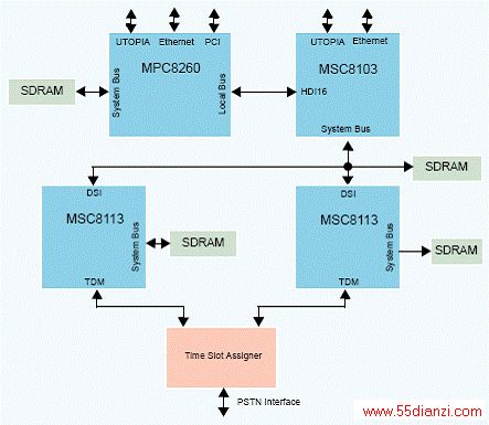
图3. 672 G.711通路媒体网关的应用案例方框图.
上一页 [1] [2]
本文关键字:通信 电子技术,电工技术 - 电子技术


