Freesale M1321x ZigBee方案
点击数:7997 次 录入时间:03-04 11:51:34 整理:http://www.55dianzi.com 电子技术
Freescale公司的MC1321x系列是ZigBee兼容的平台,它集成了用于IEEE® 802.15.4 标准的2.4GHz低功耗收发器和微控制器.收发器包括低噪音放大器,带VCO的1mW正常输出功率的功率放大器(PA),发送/接收转换开关,板内电源稳压器,以及完全扩展频谱编码和译码.而MCU则包括基于HCS08系统的微控制单元(MCU),有高达60KB的闪存和4KB RAM. MC1321x系列广泛应用在工业控制,住宅区和商业自动化,卫生保健以及消费类电子等.本文介绍了MC1321x系列的主要性能,方框图, 802.15.4 标准调制解调器方框图和MCU 方框图, RF 参数评估电路图, 采用F天线的单端口应用电路和采用F天线的双端口应用电路.
MC13211/212/213 ZigBee- Compliant Platform - 2.4 GHz Low Power Transceiver for the IEEE® 802.15.4 Standard plus Microcontroller
The MC1321x family is Freescale’s second-generation ZigBee platform which incorporates a low power 2.4 GHz radio frequency transceiver and an 8-bit microcontroller into a single 9x9x1 mm 71-pin LGA package. The MC1321x solution can be used for wireless applications from simple proprietary point-to-point connectivity to a complete ZigBee mesh network. The combination of the radio and a microcontroller in a small
footprint package allows for a cost-effective solution.
The MC1321x contains an RF transceiver which is an 802.15.4 Standard compliant radio that operates in the 2.4 GHz ISM frequency band. The transceiver includes a low noise amplifier, 1mW nominal output power, PA with internal voltage controlled oscillator (VCO),
integrated transmit/receive switch, on-board power supply regulation, and full spread-spectrum encoding and decoding.
The MC1321x also contains a microcontroller based on the HCS08 Family of Microcontroller Units (MCU), specifically the HCS08 Version A, and can provide up to
60KB of flash memory and 4KB of RAM. The onboard MCU allows the communications stack and also the application to reside on the same system-in-package (SIP). The MC1321x family is organized as follows:
The MC13211 has 16KB of flash and 1KB of RAM and is an ideal solution for low cost,
proprietary applications that require wireless point-to-point or star network connectivity. The MC13211 combined with the Freescale Simple MAC (SMAC) provides the foundation for proprietary applications by supplying the necessary source code and application examples to get users started on implementing wireless connectivity.
The MC13212 contains 32K of flash and 2KB of RAM and is intended for use with the Freescale fully compliant 802.15.4 MAC. Custom networks based on the 802.15.4 Standard MAC can be implemented to fit user needs. The 802.15.4 Standard supports star, mesh and cluster tree topologies as well as beaconed networks.
The MC13213 contains 60K of flash and 4KB of RAM and is also intended for use with the Freescale fully compliant 802.15.4 MAC and the fully ZigBee compliant Freescale BeeStack.
Applications include, but are not limited to, the following:
Residential and commercial automation
―Lighting control
―Security
―Access control
―Heating, ventilation, air-conditioning (HVAC)
―Automated meter reading (AMR)
Industrial Control
―Asset tracking and monitoring
―Homeland security
―Process management
―Environmental monitoring and control
―HVAC
―Automated meter reading
Health Care
―Patient monitoring
―Fitness monitoring
Consumer
―Human interface devices (keyboard, mice, etc.)
―Remote control
―Wireless toys
General Platform Features
802.15.4 Standard compliant on-chip transceiver/modem
―2.4GHz
―16 selectable channels
―Programmable output power
Multiple power saving modes
2V to 3.4V operating voltage with on-chip voltage regulators
-40°C to +85°C temperature range
Low external component count
Supports single 16 MHz crystal clock source operation or dual crystal operation
Support for SMAC, 802.15.4 Standard, and ZigBee software
9mm x 9mm x 1mm 71-pin LGA
Microcontroller Features
Low voltage MCU with 40 MHz low power HCS08 CPU core
Up to 60K flash memory with block protection and security and 4K RAM
―MC13211: 16KB Flash, 1KB RAM
―MC13212: 32KB Flash, 2KB RAM
―MC13213: 60KB Flash, 4KB RAM
Low power modes (Wait plus Stop2 and Stop3 modes)
Dedicated serial peripheral interface (SPI) connected internally to 802.15.4 modem
One external 4-channel (5-channel internal) 16-bit timer/pulse width modulator (TPM) module and one external 1-channel (3-channel internal) 16-bit timer/pulse width modulator module, each with selectable input capture, output capture, and PWM capability.
8-bit port keyboard interrupt (KBI)
8-channel 8-10-bit ADC
Two independent serial communication interfaces (SCI)
Multiple clock source options
―Internal clock generator (ICG) with 243 kHz oscillator that has +/-0.2% trimming resolution and +/-0.5% deviation across voltage.
―Startup oscillator of approximately 8 MHz
―External crystal or resonator
―External source from modem clock for very high accuracy source or system low-cost option
Inter-integrated circuit (IIC) interface.
In-circuit debug and flash programming available via on-chip background debug module (BDM)
―Two comparator and 9 trigger modes
―Eight deep FIFO for storing change-of-flow addresses and event-only data
―Tag and force breakpoints
―In-circuit debugging with single breakpoint
System protection features
―Programmable low voltage interrupt (LVI)
―Optional watchdog timer (COP)
―Illegal opcode detection
Up to 32 MCU GPIO with programmable pullups
RF Modem Features
Fully compliant 802.15.4 Standard transceiver supports 250 kbps O-QPSK data in 5.0 MHz channels and full spread-spectrum encode and decode
Operates on one of 16 selectable channels in the 2.4 GHz ISM band
-1 dBm to 0 dBm nominal output power, programmable from -27 dBm to +3 dBm typical
Receive sensitivity of <-92 dBm (typical) at 1% PER, 20-byte packet, much better than the 802.15.4 Standard of -85 dBm
Integrated transmit/receive switch
Dual PA ouput pairs which can be programmed for full differential single-port or dual-port
operation that supports an external LNA and/or PA.
Three low power modes for increased battery life
Programmable frequency clock output for use by MCU
Onboard trim capability for 16 MHz crystal reference oscillator eliminates need for external variable capacitors and allows for automated production frequency calibration
Four internal timer comparators available to supplement MCU timer resources
Supports both packet data mode and streaming data mode
Seven GPIO to supplement MCU GPIO
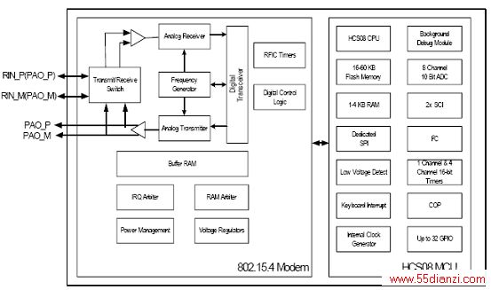
图1.MC1321x方框图
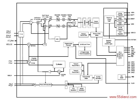
图2.802.15.4 标准调制解调器方框图
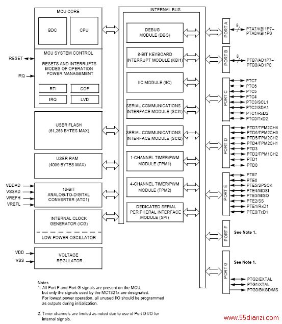
图3.MCU 方框图(HCS08, Version A)
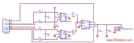
图4.RF 参数评估电路图
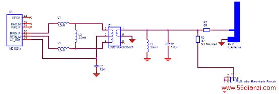
图5.采用F天线的单端口应用电路
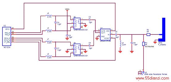
图6.采用F天线的双端口应用电路
本文关键字:暂无联系方式电子技术,电工技术 - 电子技术


